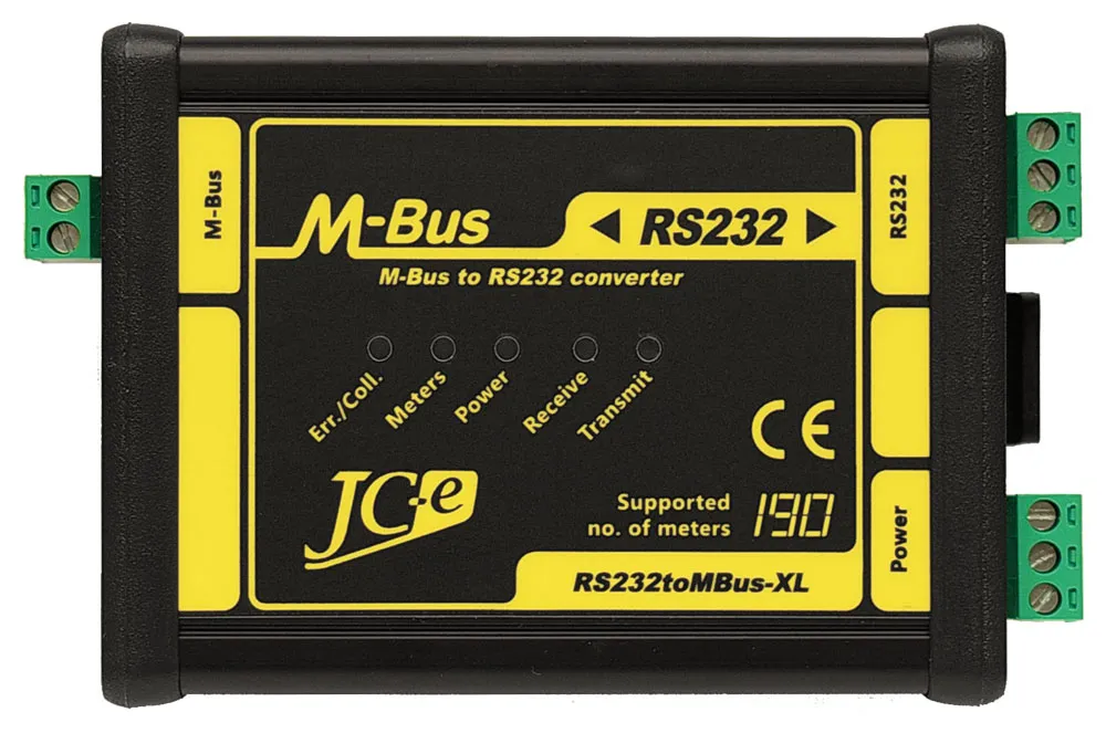
RS232toMBus-XL
RS232 to M-Bus communication converter
Application
Remote data retrieval from M-Bus devices via the RS232 serial communication line in industry and building automation. The most frequently used M-Bus slave devices are heat, water and electricity consumption meters.
Description
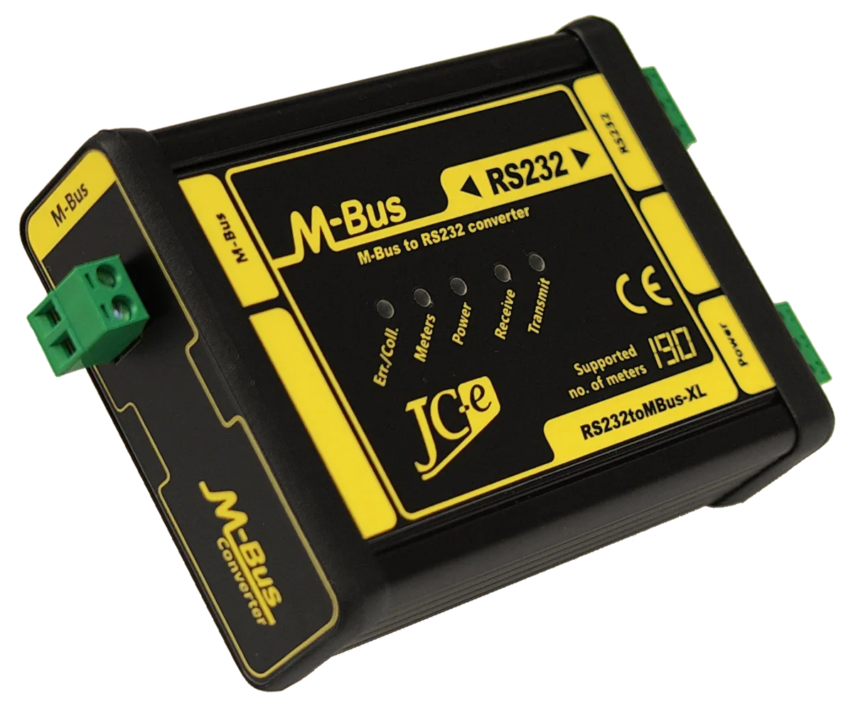
The RS232toMBus-XL converter provides a RS232 to M-Bus interface conversion. There is no change in the content of the messages or communication speed during the conversion. Depending on the converter model the maximum number of M-Bus slave devices that can be connected is 20, 45, 80, 120 or 190.
Main characteristics
The M-Bus converter features a processor controlled monitoring of internal state, power supply state and M-Bus line state. Operation and error states are indicated by status LEDs which simplify and make it easier to troubleshoot possible M-Bus communication errors.
M-Bus port
- Connection of 1 to 20, 45, 80, 120 or 190 M-Bus slave devices depending on converter model.
- Surge protection warranting above standard level of protection against overvoltage.
- Current protection against overload and short circuit on the communication line.
- External voltage protection.
- Processor controlled monitoring of M-Bus line state with LED indication for various error states.
- Indication of M-Bus slave devices reply collision.
- Indication of slave devices presence on the M-Bus line.
- Indication of M-Bus line overload, short and capacitive overload.
Power supply
- Wide range of operating DC power supply voltages 12-30V (20-30V for the XL190 model).
- Overvoltage protection.
- Processor controlled monitoring of power supply voltage with indication of its correctness and errors.
RS232
- Signals: TxD, RxD and GND
- Overvoltage protections.
- Galvanic separation from power supply and M-Bus line.
Mechanical construction
- Aluminium box with mounting on 35 mm DIN rail.
Guarantee of quality
- Each converter passes through several functional electrical tests during the production.
Additionally a communication test is performed after final assembly. - EMC certification in an accredited laboratory for industrial environment.
- Solid design and construction based on many years practical experience.
| RS232 communication interface | |
|---|---|
| Communication signals | RxD, TxD and GND |
| Protection | protection against ±15kV ESD, filters |
| Galvanic separation | >1kV from power supply, 1kV from the M-Bus line |
| Connector | terminal block with plug-in connector for wires of up to 2.5 mm² cross-section area |
| M-Bus Master communication interface | |
| Number of attachable devices – XL20 | 1 to 20 SLAVE devices, idle current max. 30mA |
| Number of attachable devices – XL45 | 1 to 45 SLAVE devices, idle current max. 67.5mA |
| Number of attachable devices – XL80 | 1 to 80 SLAVE devices, idle current max. 120mA |
| Number of attachable devices – XL120 | 1 to 120 SLAVE devices, idle current max. 180mA |
| Number of attachable devices – XL190 | 1 to 190 SLAVE devices, idle current max. 285mA |
| Baud rate | 300 – 9600 bps |
| Protection | – overvoltage protection TVS 1500W |
| – electronic protection against overloads and short circuit on the communication line | |
| – electronic protection against external voltage | |
| note: converter can withstand sustained short circuit on the communication line | |
| Galvanic separation | 1kV from power supply, 1kV from the RS232 line |
| Connector | terminal block with plug-in connector for wires of up to 2.5 mm² cross-section area |
| Power supply | |
| Recommended range of power supply voltages | |
| DC power supply | 12V to 30V, model XL190 20V to 30V |
| Maximum limits of supply voltage – permanent operation at these voltages is not recommended | |
| Minimum DC voltage | 11V – min. voltage required for converter operation |
| Maximum DC voltage | 31V – at higher the overvoltage protection starts to activate |
| Protection | – overvoltage protection TVS 1500W |
| – power supply polarity reversal protection | |
| Power consumption | 0.85W to 15W depends on converter model and number of M-Bus devices connected |
| Connector | terminal block with plug-in connector for wires of up to 2.5 mm² cross-section area |
| Status LEDs | |
| Power – green | power indication. Indicates a converter malfunction when flashing. |
| Transmit – green | indication of data transmission on the M-Bus line |
| Receive – yellow | indication of data reception on the M-Bus line |
| Meters – yellow | indication of M-Bus meters on the line |
| Err./Coll. – red | indication of error, overload, collision on the M-Bus line |
| Note: For further details on LED indication see manual. | |
| Temperature | |
| Operating range | -40°C to 70°C |
| Mechanical construction | |
| Mechanical design | aluminium box |
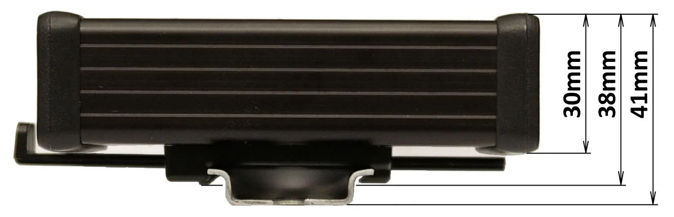
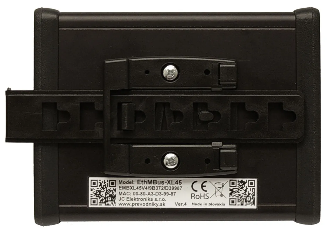
| Mounting | 35 mm DIN rail (EN 50022 top hat rail) |
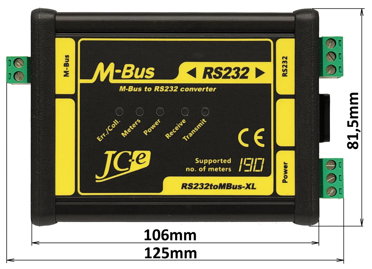
| Dimensions: height x width x length | 38 x 81.5 x 107 mm – without connectors |
| 38 x 81.5 x 125 mm – with connectors | |
| Protection classification | IP40 |
| Weight | 220g (XL20, XL45, XL80) / 240g (XL120, XL190) |
EMC compatibility of the M-Bus converter has been tested according to the following industrial environment standards.
| EMC emission tests | ||
|---|---|---|
| Standard | Test | Level |
| EN 55011 | Power line – CONDUCTED EMISSIONS 10/150 kHz – 30 MHz | Class A |
| EN 55011 | RADIATED EMISSIONS (Electric Field) 30 MHz – 1000 MHz | Class A |
| EMC immunity tests | ||
|---|---|---|
| Standard | Test | Level |
| EN 61000-4-2 | ELECTROSTATIC DISCHARGE (ESD) – Contact discharge | ± 4 kV |
| EN 61000-4-2 | ELECTROSTATIC DISCHARGE (ESD) – Air discharge | ± 8 kV |
| EN 61000-4-3 | RADIATED RADIO-FREQUENCY ELECTROMAG. FIELD 80MHz – 1GHz | 10 V/m |
| EN 61000-4-3 | RADIATED RADIO-FREQUENCY ELECTROMAG. FIELD 1.4GHz – 2GHz | 10 V/m |
| EN 61000-4-3 | RADIATED RADIO-FREQUENCY ELECTROMAG. FIELD 2GHz – 2.7GHz | 3 V/m |
| EN 61000-4-4 | ELECTRICAL FAST TRANSIENT/BURST – Power line | ± 4 kV |
| EN 61000-4-4 | ELECTRICAL FAST TRANSIENT/BURST – M-Bus, RS232 line | ± 4 kV |
| EN 61000-4-5 | SURGE IMMUNITY – Power line. Common/differential mode. | ± 1 kV / ± 500 V |
| EN 61000-4-5 | SURGE IMMUNITY – M-Bus, RS232 line. Cable shielding. | ± 4 kV |
| EN 61000-4-5 | SURGE IMMUNITY – M-Bus line. Common/differential mode.* | ± 4 kV / ± 2 kV |
| EN 61000-4-6 | CONDUCTED DISTURBANCES, INDUCED BY RADIO-FREQUENCY FIELDS 0.15MHz – 80 MHZ. M-Bus line | 10 V |
* test carried out at the request of the manufacturer. The M-Bus port has an increased durability against overvoltage. Carrying out this type of test is not required with the use of shield cable.
End user
Price list for individuals and companies which do not buy converters for resale.
Integrator
Price list for companies which buy converters for the purpose of resale to their custommers as manufacturers or suppliers.
The price list is available only to registered business partners.
Registration request.
Leaflet
Manuals
Contents
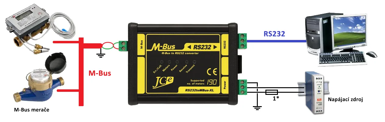
Typical application
Typical wiring of the converter with M-Bus devices, power supply and a RS232 serial communication link connection to a computer.
LED indication
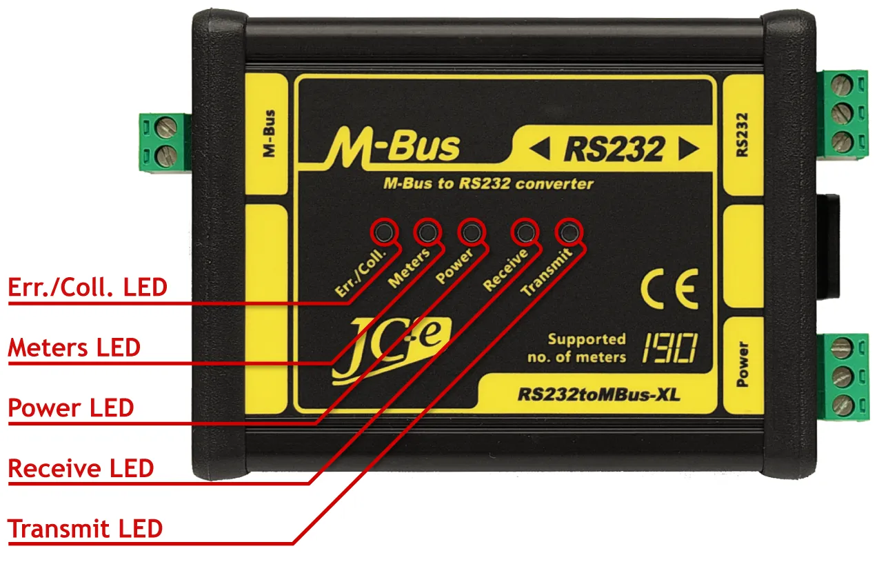
Operational states indication
| Status LEDs | State |
|---|---|
| Power LED turned on | Converter and power supply is alright. |
| Transmit LED flashing | Data is transmitted to the M-Bus line. |
| Receive LED flasing | Data is received from the M-Bus line. |
| Meters LED turned on | Load on M-Bus line. Meters are connected to the line. |
| Meters LED turned off | Disconnected M-Bus line. No meters are connected to the line. |
| Fast flashing Meters LED | Max. amount of meters on M-Bus line reached (2 meters tolerance). |
Malfunction states indication
| Status LEDs | State |
|---|---|
| Power LED flashing | Internal converter error. |
| Power LED flashing + turned on Err./Coll. LED | External voltage on M-Bus line or Internal converter error. |
| Err./Coll. LED flashing or turned on | Converter overload – too many meters, short on the M-Bus line or capacitive overload on M-Bus line (C of line > 5μF). When turning on the power – capacitive overload on M-Bus line (C of line > 1μF). Increased capacitance may be caused by meters during power up. Capacitance can afterwards fall bellow 1μF. |
| Err./Coll. LED turned on for a short while | During data reception – flashing Receive LED. Communication collision. Simultaneous reply from multiple meters. During data transmission – flashing Transmit LED. An error occurs during transmission (incorrect voltages on the M-Bus line). Internal converter error or capacitive overload on M-Bus line. |

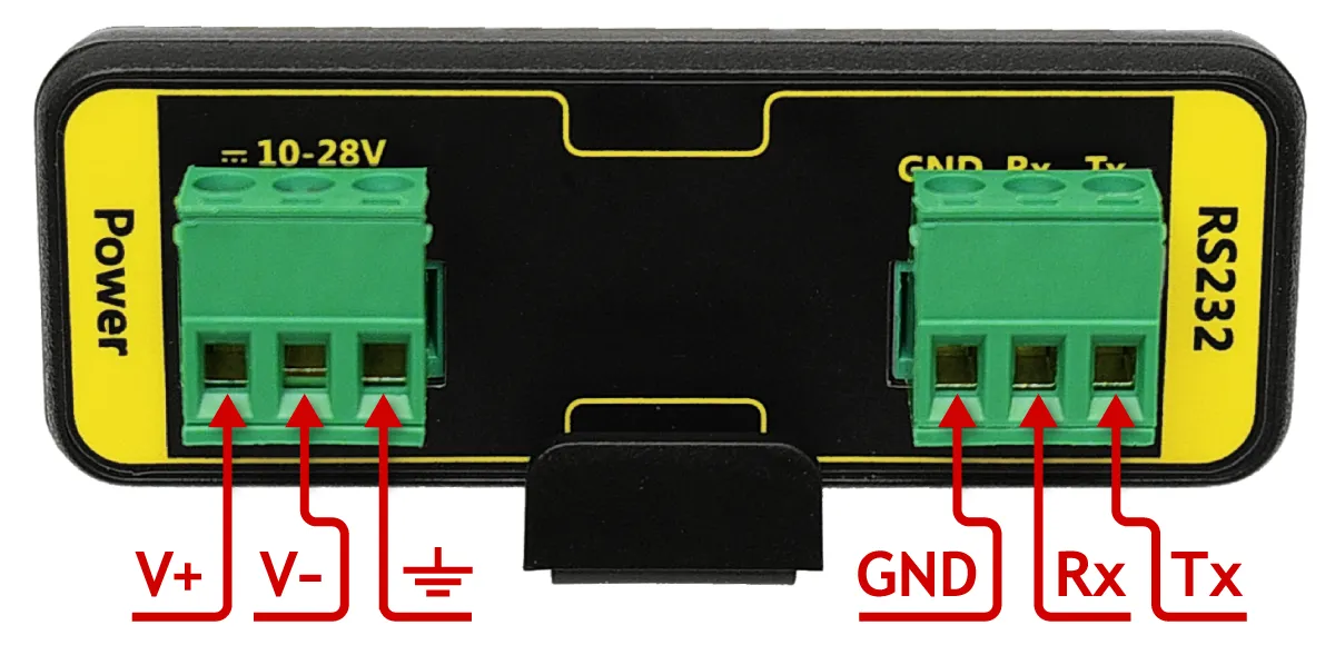
Connectors on the Power Supply and RS232 side
| Connectors | Type | |
|---|---|---|
| Power | Connector for power supply. | SH-02-5.08 |
| V+ Positive pole of the DC power supply voltage. | ||
| V- Negative pole of the DC power supply voltage. | ||
| ⏚Earth ground. | ||
| RS232 | Connector for the RS232 interface. | SH-02-5.08 |
| Rx RS232 Receive line. | ||
| Tx RS232 Transmit line. | ||
| GND RS232 ground. | ||