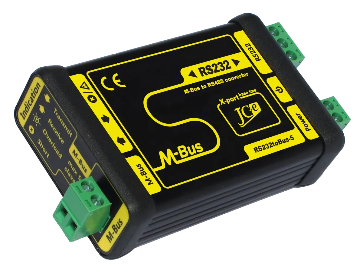
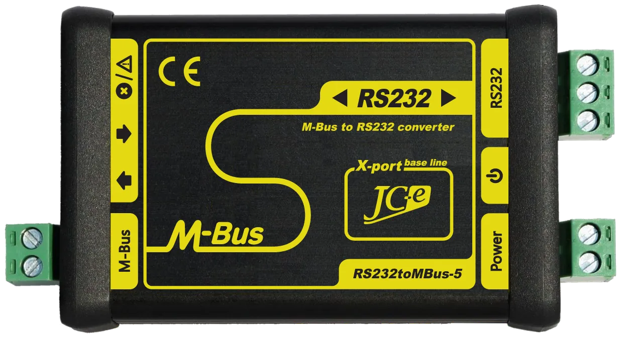
RS232toMBus-5
RS232 to M-Bus communication converter
Application
Remote data retrieval from M-Bus devices via the RS232 serial communication line in industry and building automation. The most frequently used M-Bus slave devices are heat, water and electricity consumption meters.
Description
The RS232toMBus-5 converter provides a RS232 to M-Bus interface conversion. There is no change in the content of the messages or communication speed during the conversion. The maximum number of M-Bus slave devices that can be connected is five.
Main characteristics
M-Bus port
- Connection of 1 to 5 M-Bus slave devices.
- Surge protection guaranteeing superior durability against overvoltage.
- Current protection against overload and short circuit on the communication line
with LED status indication.
Power supply
- Wide range of power supply voltages. DC 9-34V or AC 8-24V.
- Overvoltage protection and current fuse.
- LED indication of power supply.
RS232
- Signals: TxD, RxD and GND
- Protections against overvoltage.
- Galvanic separation from the power supply and also the M-Bus line.
Mechanical construction
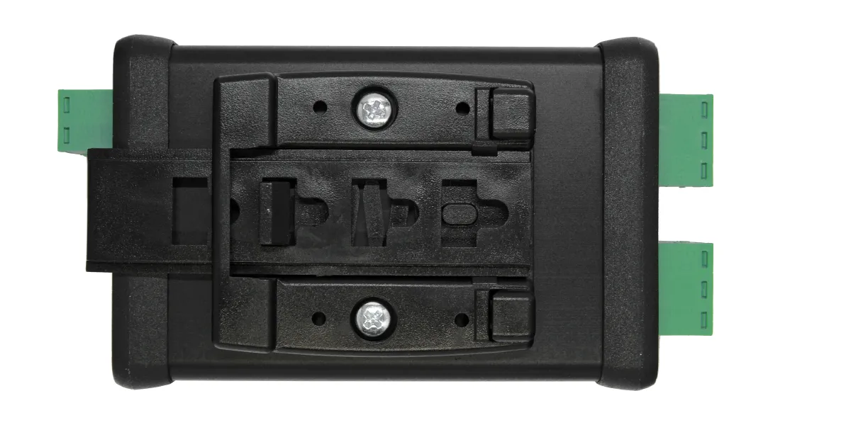
- Aluminium box with mounting on 35 mm DIN rail.
Differences from the RS232toMBus-5M converter
- More powerful overvoltage protections on the M-Bus line.
- More powerful M-Bus line driver with more efficient filters.
Length of the M-Bus line can be more then 1km. - Higher operating temperature range.
- More robust mechanical construction.
Guarantee of quality
- Each converter passes through several functional electrical tests during the production.
Additionally a communication test is performed after final assembly. - EMC certification in an accredited laboratory for industrial environment.
- Solid design and construction based on many years practical experience.
| RS232 communication interface | |
|---|---|
| Communication signals | RxD, TxD and GND |
| Protection | protection against ±15kV ESD, filters |
| Galvanic separation | 1kV from power supply, >1kV from the M-Bus line |
| Connector | terminal block with plug-in connector for wires of up to 2.5 mm² cross-section area |
| M-Bus Master communication interface | |
| Number of devices that can be connected | 1 to 5 SLAVE devices, idle current max. 7.5mA |
| Baud rate | 300 – 9600 bps |
| Protection | – overvoltage protection TVS 1500W |
| – electronic protection against overloads and short circuit on the communication line | |
| note: converter can withstand sustained short circuit on the communication line | |
| Galvanic separation | 1kV from power supply, >1kV from the RS232 line |
| Connector | terminal block with plug-in connector for wires of up to 2.5 mm² cross-section area |
| Power supply | |
| Recommended range of power supply voltages | |
| DC power supply | 9V to 34V |
| AC power supply | 8V to 24V |
| Protection | – overvoltage protection TVS 1500W |
| – overcurrent protection with a 0.3A resettable PTC fuse | |
| Power consumption | 0.4W to 1.1W Depends on M-Bus line load and power supply. |
| Connector | terminal block with plug-in connector for wires of up to 2.5 mm² cross-section area |
| Status LEDs | |
| Power – green | indication of connected supply voltage |
| Transmit – green | indication of data broadcasting on the M-Bus line |
| Receive – yellow | indication of data reception on the M-Bus line |
| Overload/Short – red | indication of M-Bus line overload – flashing (idle current > 8mA) |
| indication of short on the M-Bus line – turned on (resistance of the line < 500Ω) | |
| Temperature | |
| Operating range | -40°C to 70°C |
| Mechanical construction | |
| Mechanical design | aluminium box |
| Mounting | 35 mm DIN rail (EN 50022 top hat rail) |
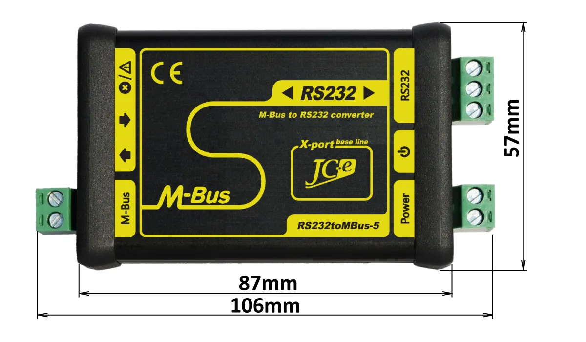
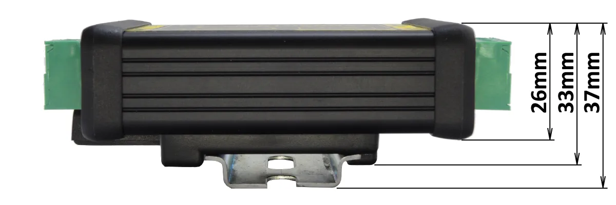
| Dimensions: height x width x length | 33 x 57 x 87 mm – without connectors |
| 33 x 57 x 106 mm – with connectors (M-Bus and Power plug-in connectors in the terminal blocks) |
|
| Protection classification | IP20 |
| Weight | 125g |
EMC compatibility of the M-Bus converter has been tested according to the following industrial environment standards.
| EMC emission tests | ||
|---|---|---|
| Standard | Test | Level |
| EN 55011 | Power line – CONDUCTED EMISSIONS 10/150 kHz – 30 MHz | Class A |
| EN 55011 | RADIATED EMISSIONS (Electric Field) 30 MHz – 1000 MHz | Class A |
| EMC immunity tests | ||
|---|---|---|
| Standard | Test | Level |
| EN 61000-4-2 | ELECTROSTATIC DISCHARGE (ESD) – Contact discharge | ± 4 kV |
| EN 61000-4-2 | ELECTROSTATIC DISCHARGE (ESD) – Air discharge | ± 8 kV |
| EN 61000-4-3 | RADIATED RADIO-FREQUENCY ELECTROMAG. FIELD 80MHz – 1GHz | 10 V/m |
| EN 61000-4-3 | RADIATED RADIO-FREQUENCY ELECTROMAG. FIELD 1.4GHz – 2GHz | 10 V/m |
| EN 61000-4-3 | RADIATED RADIO-FREQUENCY ELECTROMAG. FIELD 2GHz – 2.7GHz | 3 V/m |
| EN 61000-4-4 | ELECTRICAL FAST TRANSIENT/BURST – Power line | ± 4 kV |
| EN 61000-4-4 | ELECTRICAL FAST TRANSIENT/BURST – M-Bus, RS232 line | ± 4 kV |
| EN 61000-4-5 | SURGE IMMUNITY – Power line. Common/differential mode. | ± 1 kV / ± 1 kV |
| EN 61000-4-5 | SURGE IMMUNITY – M-Bus, RS232 line. Cable shielding. | ± 4 kV |
| EN 61000-4-5 | SURGE IMMUNITY – M-Bus line. Common/differential mode.* | ± 4 kV / ± 2 kV |
| EN 61000-4-6 | CONDUCTED DISTURBANCES, INDUCED BY RADIO-FREQUENCY FIELDS 0.15MHz – 80 MHZ. Power line and M-Bus line. | 10 V |
* test carried out at the request of the manufacturer. The M-Bus port has an increased durability against overvoltage. Carrying out this type of test is not required with the use of shield cable.
End user
Price list for individuals and companies which do not buy converters for resale.
Integrator
Price list for companies which buy converters for the purpose of resale to their custommers as manufacturers or suppliers.
The price list is available only to registered business partners.
Registration request.
Leaflet
Manuals
Contents
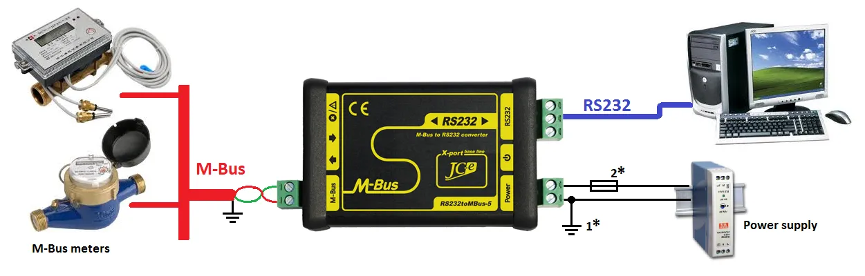
Typical application
Typical wiring of the converter with M-Bus devices, power supply and a RS232 serial communication link connection to a computer.
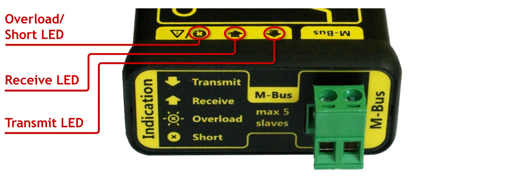
Connectors on the M-Bus side
| Connector | Type | |
|---|---|---|
| M-Bus | Connector for the M-Bus line. | SH-02-5.08 |
| Status LEDs | Color | |
| Transmit | Indication of transmission on the M-Bus line. | green |
| Receive | Indication of reception on the M-Bus line. | yellow |
| Overload/Short | Indication of overload or short circuit on the M-Bus line. | red |
| – during overload the LED flashes alternately with Receive LED, I > 8mA | ||
| – short circuit is indicated with the LED turned on permanently, resistance of the M-Bus line < 500Ω | ||
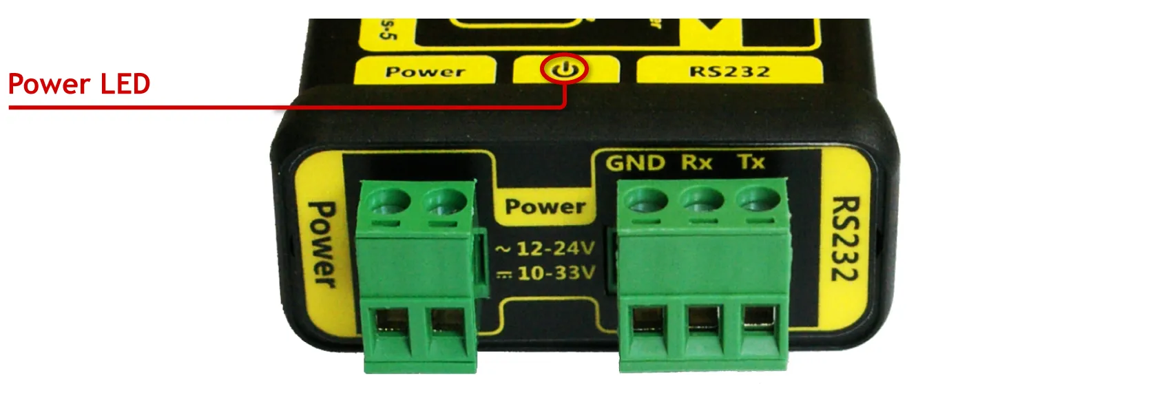
Connectors on the Power Supply and RS232 side
| Connectors | Type | |
|---|---|---|
| Power | Connector for power supply. | SV-02-5.08 |
| RS232 | Connector for the RS232 interface. | SV-02-5.08 |
| Status LEDs | Color | |
| Power | Indication of correct power supply voltage. | green |