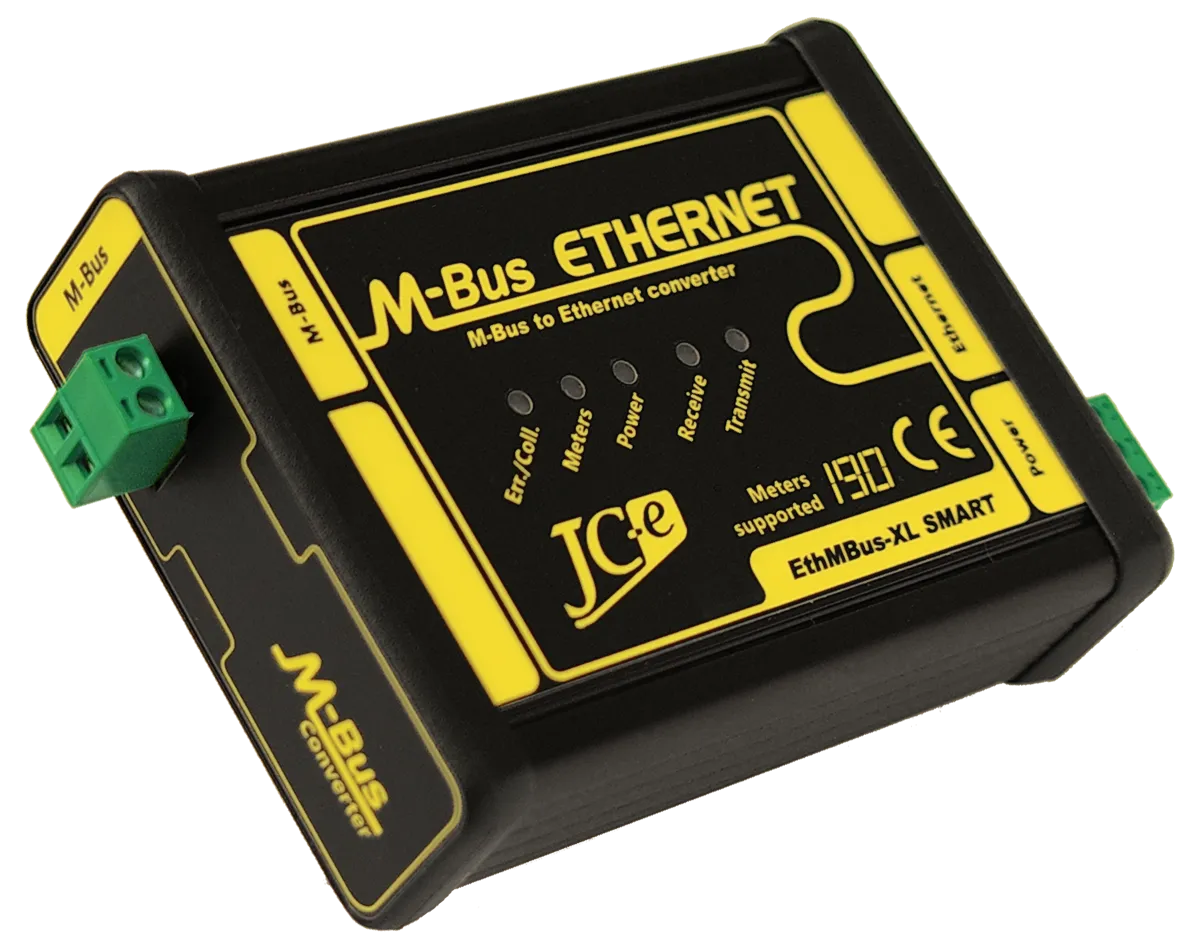
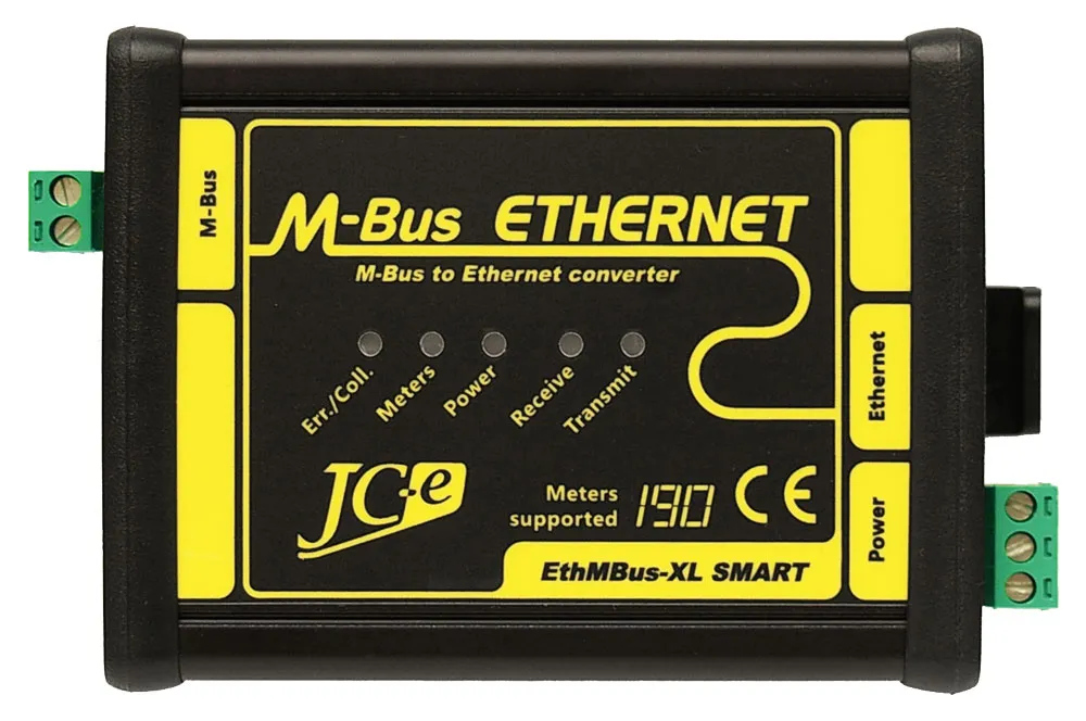
EthMBus-XL SMART
Ethernet to M-Bus communication converter
Converter for SMART metering
Designed for remote communication with M-Bus meters using the Ethernet computer network in industry, building automation.
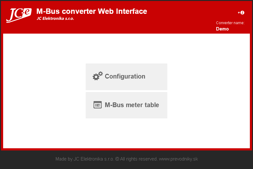
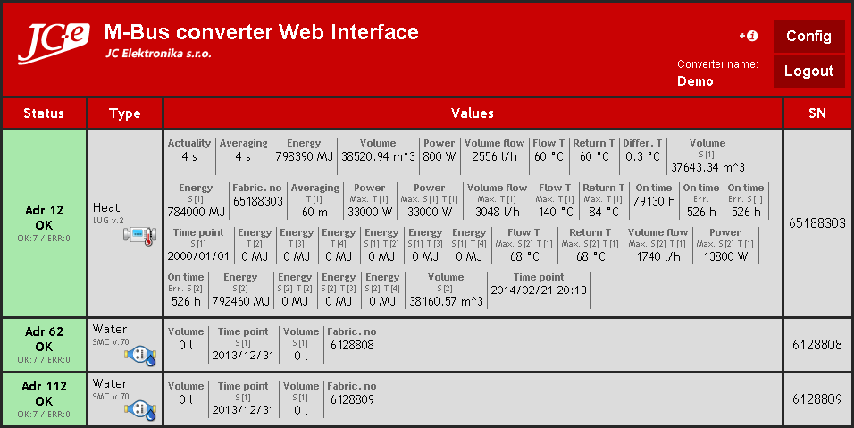
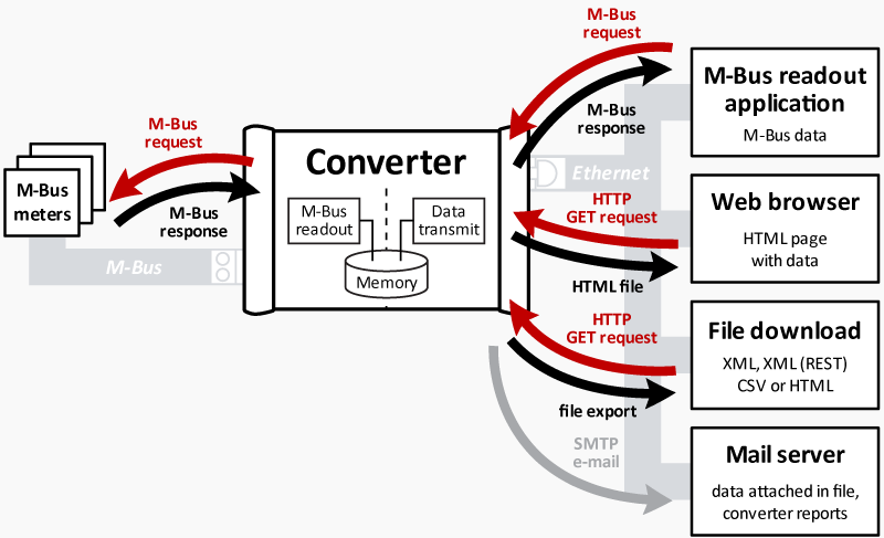
In the Smart M-Bus mode the converter works as a server. It communicates with the M-Bus meters independently, processes their data and stores it in its own memory. The meter data is simultaneously available in form of:
- table on a webpage
- xml, xml(REST) and csv export
- M-Bus protocol communication
- e-mail with attached xml, csv exports
- exports uploaded to an FTP server
Document with detailed functionality description
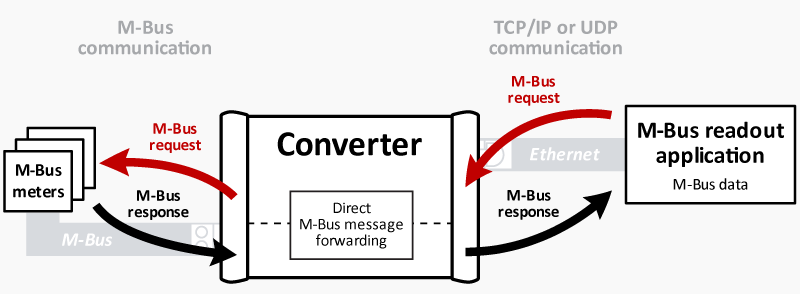
In the basic mode the converter works as a transparent gateway for transfer of M-Bus messages using TCP or UDP Ethernet protocols.
Notice: The Smart M-Bus mode for converter models XL120 and XL190 is limited to 92 addresses for M-Bus slave devices in the current version of firmware (Feb 2026 and newer).
Changes in firmware
The latest version of firmware adds important improvements and better functionality to existing features.
The list of changes is available in this file.
Main characteristics
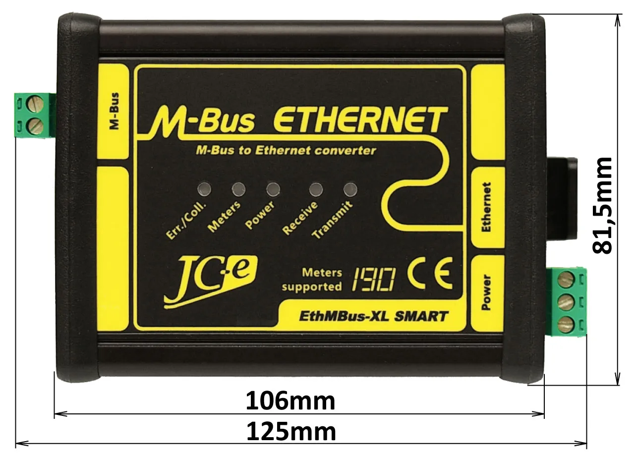
The M-Bus converter features a processor controlled monitoring of internal state, power supply state and M-Bus line state. Operation and error states are indicated by status LEDs which simplify and make it easier to troubleshoot possible M-Bus communication errors.
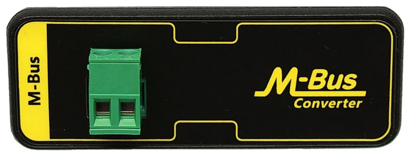
M-Bus port
- Connection of 1 to 20, 45, 80, 120 or 190 M-Bus slave devices depending on converter model.
The most commonly used devices are heat, water, gas and electricity consumption meters. - Surge protection warranting above standard level of protection against overvoltage.
- Current protection against overload and short circuit on the communication line.
- External voltage protection.
- Processor controlled monitoring of M-Bus line state with LED indication for various error states.
- Indication of M-Bus slave devices reply collision.
- Indication of slave devices presence on the M-Bus line.
- Indication of M-Bus line overload, short and capacitive overload.
Power supply
- Wide range of operating DC power supply voltages 12-30V (20-30V for the XL190 model).
- Overvoltage protection.
- Processor controlled monitoring of power supply voltage with indication of its correctness and errors.
Ethernet
- TCP, UDP protocols and virtual COM port software.
- 10/100BASE-TX ethernet port, RJ45 connector.
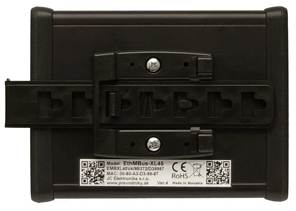
Mechanical construction
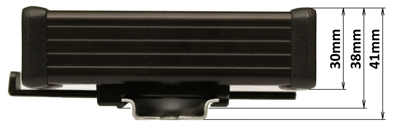
- Aluminium box with mounting on 35 mm DIN rail.
Main software characteristics
Transparent gateway mode:
- TCP/IP connection
- server or client mode
- backup IP addresses for connection
- connection to a web address (DNS)
- UDP connection
Smart M-Bus application mode:
- web page with meter data
- xml, xml(REST), csv exports
- e-mails with exports and service information
- exports uploaded to an FTP server
Software functions
- Configuration of the converter through a web interface or Telnet.
- TCP and UDP communication in server or client mode including connection backup IP addresses.
- DNS support (host name instead of IP)
- Logging of Ethernet activity and error states.
- Search for meter addresses and their change (meter must support this functionality).
- Success rate statistics for communication with individual meters.
Guarantee of quality
- Each converter passes through several functional electrical tests during the production.
- Additionally a communication test is performed after final assembly.
- EMC certification in an accredited laboratory for industrial environment.
- Solid design and construction based on many years practical experience.
| Ethernet communications interface | |
|---|---|
| Communications interface | 10BASE-T or 100BASE-TX (auto-sensing) |
| Communication protocols | ARP, UDP, TCP, ICMP, Telnet, TFTP, AutoIP, DHCP, HTTP, SNMP |
| Connector | RJ45 |
| Compatibility | Ethernet: Version 2.0/IEEE 802.3 |
| M-Bus Master communication interface | |
| Number of attachable devices – XL20 | 1 to 20 SLAVE devices, idle current max. 30mA |
| Number of attachable devices – XL45 | 1 to 45 SLAVE devices, idle current max. 67.5mA |
| Number of attachable devices – XL80 | 1 to 80 SLAVE devices, idle current max. 120mA |
| Number of attachable devices – XL120 | 1 to 120 SLAVE devices, idle current max. 180mA |
| Number of attachable devices – XL190 | 1 to 190 SLAVE devices, idle current max. 285mA |
| Baud rate | 300 – 9600 bps |
| Protection | – overvoltage protection TVS 1500W – electronic protection against external voltage – electronic protection against overloads and short circuit on the communication line note: converter can withstand sustained short circuit on the communication line |
| Galvanic separation | up to 1kV from power supply, more than 1kV from Ethernet |
| Connector | terminal block with plug-in connector for wires of up to 2.5 mm2 cross-section area |
| Power supply | |
| Recommended range of power supply voltages | |
| DC power supply | 12V to 30V, model XL190 20V to 30V |
| Maximum limits of supply voltage – permanent operation at these voltages is not recommended | |
| Minimum DC voltage | 11V – min. voltage required for converter operation |
| Maximum DC voltage | 31V – at higher the overvoltage protection starts to activate |
| Protection | – overvoltage protection TVS 1500W – power supply polarity reversal protection |
| Power consumption | 1.8W to 16W depends on converter model and number of M-Bus devices |
| Connector | terminal block with plug-in connector for wires of up to 2.5 mm2 cross-section area |
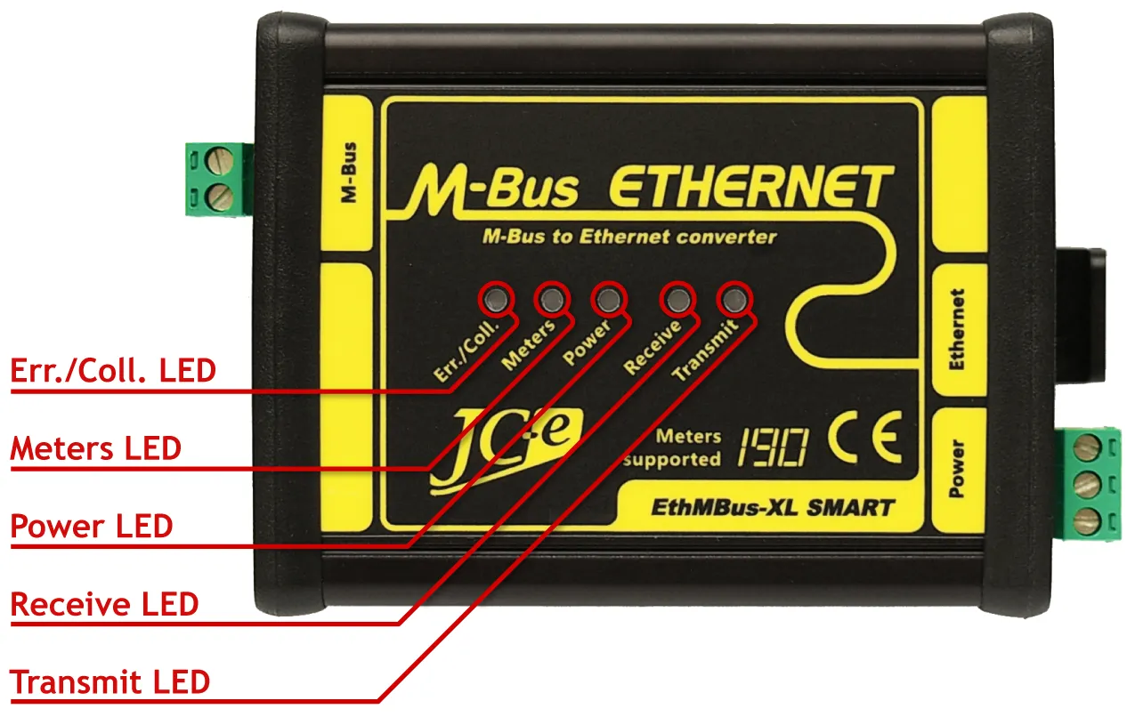
| Status LEDs | |
| Power – green | power indication. Indicates a converter malfunction when flashing. |
| Transmit – green | indication of data transmission on the M-Bus line |
| Receive – yellow | indication of data reception on the M-Bus line |
| Meters – yellow | indication of M-Bus meters on the line |
| Err./Coll. – red | indication of error, overload, collision on the M-Bus line |
| Note: For further details on LED indication see manual. | |
| Temperature | |
| Operating range | -40°C to 60°C |
| Mechanical construction | |
| Mechanical design | aluminium box |
| Mounting | 35 mm DIN rail (EN 50022 top hat rail) |
| Dimensions: height x width x length | 38 x 81.5 x 107 mm – without connectors 38 x 81.5 x 125 mm – with connectors |
| Protection classification | IP40 |
| Weight | 230g (XL20, XL45, XL80) 250g (XL120, XL190) |
EMC compatibility of the M-Bus converter has been tested according to the following industrial environment standards.
| EMC emission tests | ||
|---|---|---|
| Standard | Test | Level |
| EN 55011 | Power line – CONDUCTED EMISSIONS 10/150 kHz – 30 MHz | Class A |
| EN 55011 | RADIATED EMISSIONS (Electric Field) 30 MHz – 1000 MHz | Class A |
| EMC immunity tests | ||
| Standard | Test | Level |
| EN 61000-4-2 | ELECTROSTATIC DISCHARGE (ESD) – Contact discharge | ± 4 kV |
| EN 61000-4-2 | ELECTROSTATIC DISCHARGE (ESD) – Air discharge | ± 8 kV |
| EN 61000-4-3 | RADIATED RADIO-FREQUENCY ELECTROMAG. FIELD 80MHz – 1GHz | 10 V/m |
| EN 61000-4-3 | RADIATED RADIO-FREQUENCY ELECTROMAG. FIELD 1.4GHz – 2GHz | 10 V/m |
| EN 61000-4-3 | RADIATED RADIO-FREQUENCY ELECTROMAG. FIELD 2GHz – 2.7GHz | 3 V/m |
| EN 61000-4-4 | ELECTRICAL FAST TRANSIENT/BURST – Power line | ± 4 kV |
| EN 61000-4-4 | ELECTRICAL FAST TRANSIENT/BURST – M-Bus line | ± 4 kV |
| EN 61000-4-5 | SURGE IMMUNITY – Power line. Common/differential mode. | ± 1 kV / ± 500 V |
| EN 61000-4-5 | SURGE IMMUNITY – M-Bus line. Cable shielding. | ± 4 kV |
| EN 61000-4-5 | SURGE IMMUNITY – M-Bus line. Common/differential mode.* | ± 4 kV / ± 2 kV |
| EN 61000-4-6 | CONDUCTED DISTURBANCES, INDUCED BY RADIO-FREQUENCY FIELDS 0.15MHz – 80 MHZ. M-Bus line. |
10 V |
* test carried out at the request of the manufacturer. The M-Bus port has an increased durability against overvoltage. Carrying out this type of test is not required with the use of shield cable.
End user
Price list for individuals and companies which do not buy converters for resale.
Integrator
Price list for companies which buy converters for the purpose of resale to their custommers as manufacturers or suppliers.
The price list is available only to registered business partners.
Registration request.
Leaflet
Manuals
Short overview of modes and functions
Readout software
Excel® file for M-Bus data collection and processing
Manual for the data collecting Excel® file
Lantronix utilities
SW application from Lantronix for advanced configuration of the converters
SW application for creating a virtual COM port from Lantronix
Warning: Lantronix Com Port Redirector doesn’t work with LITE converters. Those use a different application to provide this type of functionality.
Contents
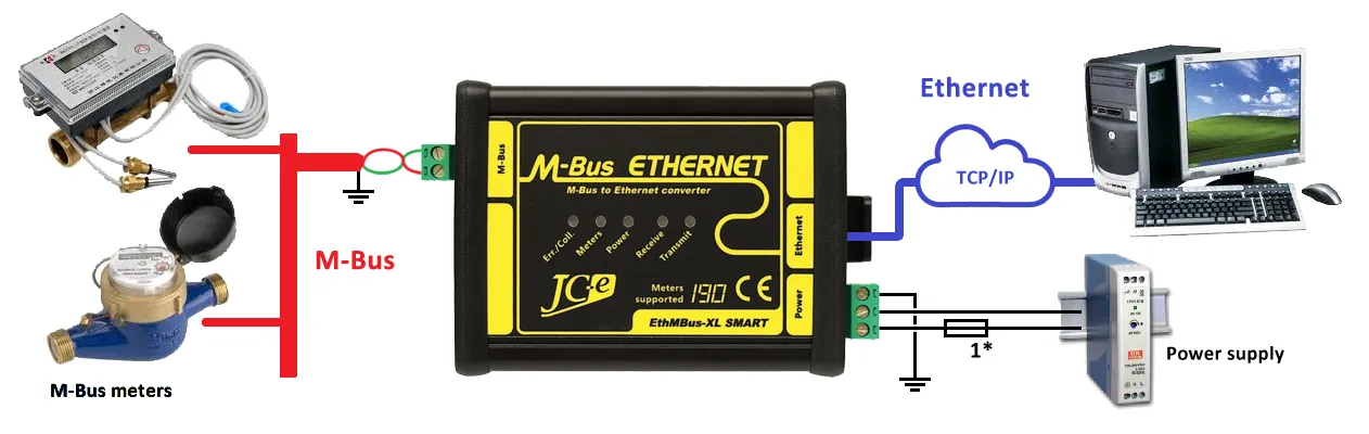
Typical application
Typical wiring of the converter with M-Bus devices, power supply and Ethernet network connection to a computer.
LED indication
Operational states indication
| Status LEDs | State |
|---|---|
| Power LED turned on | Converter and power supply is alright. |
| Transmit LED flashing | Data is transmitted to the M-Bus line. |
| Receive LED flashing | Data is received from the M-Bus line. |
| Meters LED turned on | Load on M-Bus line. Meters are connected to the line. |
| Meters LED turned off | Disconnected M-Bus line. No meters are connected to the line. |
| Fast flashing Meters LED | Max. amount of meters on M-Bus line reached (2 meters tolerance). |
Malfunction states indication
| Status LEDs | State |
|---|---|
| Power LED flashing | Internal converter error. |
| Power LED flashing + turned on Err./Coll. LED | External voltage on M-Bus line or Internal converter error. |
| Err./Coll. LED flashing or turned on | Converter overload – too many meters, short on the M-Bus line or capacitive overload on M-Bus line (C of line > 5μF). When turning on the power – capacitive overload on M-Bus line (C of line > 1μF). Increased capacitance may be caused by meters during power up. Capacitance can afterwards fall bellow 1μF. |
| Err./Coll. LED turned on for a short while | During data reception – flashing Receive LED. Communication collision. Simultaneous reply from multiple meters. During data transmission – flashing Transmit LED. An error occurs during transmission (incorrect voltages on the M-Bus line). Internal converter error or capacitive overload on M-Bus line. |
Connectors on the Power Supply and Ethernet side
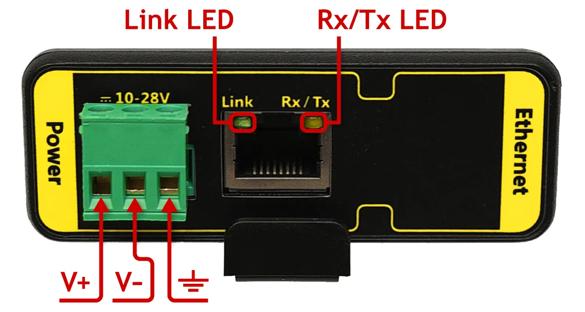
| Connectors | Type | |
|---|---|---|
| Power | Connector for power supply. | SH-02-5,08 |
| V+ Positive pole of the DC power supply voltage. | ||
| V- Negative pole of the DC power supply voltage. | ||
| ⏚ Earth ground. | ||
| Ethernet RJ45 | Connector for Ethernet. | RJ45 |
| Status LEDs | Color | |
| Link | 10Mbps connection speed | orange |
| 100Mbps connection speed | green | |
| Rx/Tx | Half-duplex | orange |
| Full-duplex | green | |